Spillway
General
Dam outlet works consist generally of spillways and bottom (high-head) outlets. Spillways are basically dam appurtenances ensuring a safe passage of floods from the reservoir into the downstream river reach. The spillway design depends primarily on the design flood, dam type and location, and reservoir size and operation. The design of bottom outlet works depends primarily on the purpose of the reservoir and the sediment inflow and deposition in the reservoir. Spillways may be classified in several ways: according to function as (main) service, emergency and auxiliary spillways; according to mode of control as free (uncontrolled) or gated (controlled) spillways; according to hydraulic criteria, i.e. type, as overfall, side channel, chute, shaft, siphon and tunnel spillways. In the following text this last type classification will be used.
Apart from economics, the main factors governing the choice of spillway for a given project are the reliability and accuracy of flood prediction, the duration and amount of spillage, seismicity of project site, topography and geology, and the dam type.
Spillways are structures constructed to provide safe release of flood water from a dam to a downstream are, normally the river on which the dam has been constructed.
Every reservoir has a certain capacity to store water. If the reservoir is full and flood waters enter the same, the reservoir level will go up and may eventually result in over-topping of the dam. To avoid this situation, the flood to be passed into the downstream and this is done by providing a spillway which draws water from the top of reservoir. A spillway can be a part of the dam or separate from it.
Spillway can be controlled or uncontrolled. A controlled spillway is provided with gates which can be raised or lowered. Controlled spillway has certain advantages as will be clear from the discussion that follows. When a reservoir is full, its water level will be the same as the crest level of the spillway. This is the normal reservoir level. If a flood enters the reservoir at this time, the water level will start going up and simultaneously
water will start glowing out through the spillway. The rise in water level in the reservoir will continue for some time and so will the discharge over the spillway. After reaching a maximum, the reservoir level will come down and eventually come back to the normal reservoir level.
2.2. Component Part of Spillway
A spillway generally has the following component parts
1. Entrance channel
2. Control structure
3. Discharge channel (or waterway)
4. Terminal structure (Energy Dissipator)
5. Exit channel
However, entrance channel and exit channel may not be required for some spillway.
2.2.1. Entrance Channel
Entrance channels are required in those type of spillways in which the control structure is away from the reservoir. The entrance structure draws water from the reservoir and carries it to the control structure. Entrance channels are not required for spillways which draw water directly from the reservoir.
2.2.2. Control Structure
Control structure is a component of a spillway. It regulates and control the surplus water from the reservoir. The control structure is designed such that it does not permit the outflow from the reservoir when the water level is lower than a predetermined level but permits the outflow as soon as the water level rise above that level.
Generally, the control structure is located at the upstream end of the spillway structure. However, in some cases, the control structure may be at the downstream end of the spillway structure. For example, in a shaft (or morning glory) spillway, the downstream tunnel controls the outflow at higher heads.
The control structure usually consists of either an orifice or a weir. In most of the spillways, the control structure is an overflow crest may be straight, curved, U-shaped, semi-circular or circular. The straight, ogee-shaped crests are mostly commonly use in spillway.
2.2.3. Discharge Channel or Waterway
The outflow released through the control structure is usually conveyed to the terminal structure through a discharge channel or waterway. Thus, the discharge channel conveys the water safely from the control structure to the river downstream. It is also called conveyance structure. The conveyance structure may have different forms. It is usually the downstream face of an overflow darn for the spillway constructed as an overflow spillway in the body of the dam. It may be in the form of an open channel, a closed conduit placed through or under a dam, or a tunnel excavated through an abutment, depending upon the type of spillways, the discharge channel may have a variety of cross-section, depending upon the geologic and topographic characteristics of the site and the hydraulic requirements.
2.2.4. Terminal Structure or Energy Dissipator
When the water flows from the reservoir over the spillway, the static energy is converted into the kinetic energy. This results in very high velocity of flow at the downstream end of the spillway. It may cause serious scour at the downstream end. It may also damage the dam, the spillway and other appurtenant structures. It is, therefore, necessary that the high energy of flow must be dissipated before the flow is returned to the river downstream. Terminal structure (or energy dissipator) are provided at the downstream end of the discharge channel to dissipate the excess energy. Generally, a hydraulic jump basin, a roller bucket, a ski-jump bucket, or some other suitable energy dissipating device is provided for the dissipation of excess energy. However, of the stream bed consists of an erosion-resistant strong rock, the overflowing water from the spillway may be delivered directly to the river downstream without a terminal structure.
2.2.5. Exit Channel
In some types of spillway, the exit channels are provided to convey the spillway discharge from the terminal structure to the river downstream. However, an exit channel is not required for the spillways which discharge water directly into the river downstream. On the other hand, in the case of spillways placed through abutments, saddles or ridges, the exit channel is usually required.
2.3. Classification of Spillways
The spillways can be classified into different types based on the various criteria, as explained below.
2.3.1. Classification Base on Purpose
1. Main (or service) spillway
2. Auxiliary spillway
3. Emergency spillway
2.3.2. Classification Base on Control
1. Controlled (or gated) spillway
2. Uncontrol (or ungated) spillway
2.3.3. Classification Base on Prominent Feature
1. Free overfall (or straight drop) spillway
2. Overflow or Ogee spillway
3. Chute (or open channel or trough) spillway
4. Side-channel spillway
5. Shaft (or morning glory) spillway
6. Siphon spillway
7. Conduit (or tunnel) spillway
8. Cascade spillway
2.3.3.1. Free overfall spillway
This is simplest types of spillway which is constructed in the form of low height weir having downstream face either vertical. Water drops freely from the crest and the underside of the falling nappe is ventilated sufficiently to prevent a pulsating, fluctuating, jet. Occasionally, the crest is extended in the form of an overhanging lip (similar to that provided in notch falls) to direct the small discharge away from the face of the overfall section. However, after sometime, the falling jet will form a deep plunge pool. Where erosion is not permissible, a low secondary dam may be constructed to create an artificial pool, or a concrete apron may be provided. Of tailwater depths are sufficient, a hydraulic jump will form when the free jet falls on the flat apron. This type of spillway is not recommended for height head since the vibrations caused by piping or undermining. Free overfall spillway shape and water profile are shown in figure (2.1).

Figure (2.1) Free Overflow Spillway
2.3.3.2. Overflow or ogee spillway
It is the overflow type spillway which has a controlled weir and is ogee-shaped(S-shaped) in profile as shown in Figure (2.2). It is shaped such that it follows the lower surface of a horizontal jet emerging from a sharp crested weir. The pressure at the ogee crest remains atmospheric at the design head. At lower head, the pressure on the ogee crest becomes positive which results into the backwater effect and this backwater effect reduces the discharge while at the higher head pressure on the crest becomes negative causing backwater effect to increase the discharge.

Figure (2.2) Ogee Spillway
2.3.3.3. Chute spillway
Chute spillway is also known as trough Spillway. The function of chute spillway is to prevent damage to the valley walls that could endanger the dams. It consists of steeply sloping open channel which is made up of reinforced concrete slab. The Spillway is sometimes of constant width, but is usually narrowed for economy and then widened near the end to reduce the discharging velocity. Chute spillway is shown in Figure (2.3).

Figure (2.3) Chute Spillway
2.3.3.4. Side-channel spillway
It is similar to the chute spillway but the only difference between it and chute spillway is that in a chute spillway, the water flows at right angles to the weir crest after spilling over it whereas in a side channel spillway the flow of water is turned by 90 degrees such that it flows to the weir crest. Shown in Figure (2.4).

Figure (2.4) Side-channel Spillway
2.3.3.5. Shaft or morning glory spillway
In the shaft spillway, the water from the reservoir enters into a vertical shaft which conveys the water into a horizontal tunnel. The horizontal or the conduit may be taken either through the body of dam or through the underground. Shaft or morning glory spillway is shown in Figure (2.5).

Figure (2.5) Shaft or Morning Glory Spillway
2.3.3.6. Siphon spillway
A siphon spillway operates on the principle of siphonic action. Siphon spillway consists of siphon pipe in which one end is kept on the upstream side and is in contact with the reservoir whereas the other end spills water on the downstream side. Siphon spillway is shown in figure (2.6).

Figure (2.6) Siphon Spillway
2.3.3.7. Conduit (or tunnel) spillway
A conduit Spill-way consist of a closed conduit to carry the flood discharge to the downstream channel. It is constructed in the abutment or under the dam. The closed conduit may take the form of a vertical or inclined shaft, a horizontal tunnel, or a conduit constructed in an open cut and then covered, as shown in Figure (2.7). Such a spill-way is suitable for dam sites in narrow canyons with steep abutments.

Figure (2.7) Conduit Spillway
2.3.3.8. Cascade spillway
In case of very high dams, the kinetic energy at the toe of the dam will be very high and the tail water depth in the river may not be adequate for a single-fall hydraulic jump or roller bucket stilling basin.
Narrow and curved canyons consisting of fractured rock would not be suitable for trajectory buckets. In such situations, especially for high earth and rock-fill dams for which spillway is a major structure, possibility of providing a cascade of falls with a stilling basin at each fall, Figure (2.8), must be considered.

Figure (2.8) Cascade Spillway
2.4. Energy Dissipator
Water flowing over a spillway has a very height kinetic energy because of the conversion of the entire potential energy to the kinetic energy. If the water following with such a high velocity is discharged directly into downstream, serious scour of the channel bed may occur. If the scour is not controlled, it may extend backward and may endanger the spillway and the dam. In order to protect the channel bed against scour, the kinetic energy of water should be dissipated before it is discharge into downstream channel. The energy-dissipating devices can be broadly classified into two types.
1. Devices using a hydraulic jump for the dissipation of energy
2. Devices using a bucket for the dissipation of energy.
The choice of the energy-dissipating device at a particular spillway is governed by the tail water depth and the characteristics of the hydraulic jump, if formed, at the toe. If the tail water depth at the site is not approximately equal to that required for a perfect hydraulic jump, a bucket-type energy dissipating device is usually provided.
2.5. Characteristics of A Hydraulic Jump
Hydraulic jump is a sudden and turbulent rise of water which occurs in an open channel when the flow changes from the supercritical flow state to the subcritical state. It is accompanied by the formation of extremely turbulent rollers and considerable dissipation of energy. Thus, a hydraulic jump is a very effective means of dissipation of energy below spillways.
2.6. Types of jumps
Basically, a hydraulic jump occurs in many types depending on topographical features and bed surface roughness and many other natural interface relations. This hydraulic jump types can be probably expressed based on Froude’s number. Types of jumps are as following jumps.
1. Undular Jump
2. Weak Jump
3. Oscillating Jump
4. Steady Jump
5. Strong Jump
2.6.1. Undular Jump
An undular jump is formed when Froude’s number 1.0 <F1<1.70. In an undular jump, the water surface shows some undulation. The energy dissipation is about 5%. Undular Jump is irregular, not properly formed and there are certain turbulences in water particles. Undular Jump form is shown in figure (2.9).

Figure (2.9) Undular Jump
2.6.2. Weak Jump
In figure (2.10), weak jump takes place when the velocity in water is very less and the water particles cannot be stable and flows in various ways. When F1 = 1.70 to 2.50, a weak hydraulic jump occurs. The energy dissipation is about 20%.

Figure (2.10) Weak Jump
2.6.3. Oscillating Jump
Oscillating jump forms when an oscillating jet enter into super critical state and there the number of particles starts oscillating in clockwise or either anticlockwise direction, forming slighter tides or waves to the top surface. Also, the flow is dependent on heavy blow of air in one direction, shown in Figure (2.11). An oscillating jump occurs when F1 = 2.50 to 4.50. The energy dissipation is between 20 to 40%.
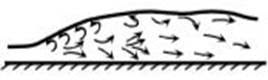
Figure (2.11) Oscillating Jump
2.6.4. Steady Jump
In steady jump, the bed surface is quite rough so the particles start to tend in one direction with heavy velocity and turbulence, frictional losses are more in this type of jump, shown in Figure (2.12). A steady jump occurs when F1 = 4.50 to 9.0. The energy dissipation is between 20 to 40%.

Figure (2.12) Steady Jump
2.6.5. Strong Jump
Strong jump is a perfect jump formed when frictional losses are more, air pressure division is equal and velocity is very high that losses take place, shown in Figure (2.13). The water changes its state from super critical to subcritical in very shorter length when compared to all other types of hydraulic jumps. A strong jump occurs when F1> 9.0. The energy dissipation between 70 to 85%. Because of rough action, a strong jump is avoided in spillways, as far as possible.

Figure (2.13) Strong Jump
2.6.6. Jump Height Curve (JHC) and Tail Water Rating Curve (TWRC)
Definition & terminology Rating curve, also known as stage–discharge curve, is a graph showing the relation between the water height (stage), and the volumetric flow-rate (discharge). Channels and hydraulic structures can have rating curves.
2.7. Location of A Hydraulic Jump
The location of hydraulic jump will depend upon the relative magnitudes of jump height curve (JHC) y2 and tail water rating curve (TWRC) y2'(yt). There are five cases, depending upon the relative position of JHC and TWRC. Location of a Hydraulic Jump is shown in Figure (2.14).

Figure (2.14)
2.7.1. Case-1: JHC and TWRC coincide through
In this case JHC and TWRC curves coincide for all discharges. Under Figure (2.15), Show Case-1 hydraulic jump is shown. As the tail water y2’ is exactly equal to the sequent depth y2 required for the formation of hydraulic jump, a perfect jump formed just at the toe of the spillway.

Figure (2.15) Case-1
2.7.2. Case 2 TWRC always lower than JHC
In this case, the tail water rating curve (TWRC) is below the jump height curve JHC for all discharges, it is shown in Figure (2.16). Such a condition occurs when the tail water is carried away quickly due to a rapid or a fall somewhere on the downstream of the spillway. In this case, the jump will be located at a point on the downstream of the toe of spillway. The high velocity jet would sweep down the toe and scour the river bed. Therefore, severe erosion may occur in the portion of the river between the spill way and the section where the hydraulic jump is formed.

Figure (2.16) Case-2
2.7.3. Case-3 TWRC always higher than JHC
In this case, the tail water rating curve is above the jump height curve for all discharges, it is shown in Figure (2.17). This condition usually occurs when the river cross-section on the downstream of the spillway is narrow and therefore the tail water backs up. The hydraulic jump in this case is located upstream of the toe on the spillway face. The hydraulic jump is drowned or submerged, and the high velocity jet dives under the tail water. The energy dissipation in a drowned hydraulic jump is not good.

Figure (2.17) Case-3
2.7.4. Case-4 TWRC lower than JHC at low discharges, but higher at high discharges
In this case, the tail water rating curve is lower than the jump height curve at low discharges then remains higher than the jump height; but it becomes higher at a particular discharge and curve, it is shown in Figure (2.18).
It is a combination of cases 2 and 3. The hydraulic jump is formed further downstream of the toe at low discharge, as in the case 2; but at higher discharges, it is
drowned as in the case 3.

Figure (2.18) Case-4
2.7.5. Case-5 TWRC higher than JHC at low discharges, but lower at high discharge
It is also combination of cases 3 and 2. However, in this case, at low discharges, the jump is downed; whereas at high discharges, it is formed further downstream of the toe. It is shown in Figure (2.19).

Figure (2.19) Case-5
2.8. Stilling Basins
A stilling basin is a basin-like structure in which all or a part of the energy is dissipated. In a stilling basin, the kinetic energy causes turbulence and it is ultimately lost as heat energy. The stilling basins commonly used for spillways are of the hydraulic jump type, in which dissipation of energy is accomplished by a hydraulic jump.
2.8.1. Chute Blocks
These are triangular blocks with their top surfaces horizontal. These are installed at the toe of the spillway just at upstream end of the stilling basin. They act as a serrated device at entrance to the stilling basin. They furrow the incoming jet and lift a portion of it above the floor. These blocks stabilize the jump and thus improve its performance. These also decrease the length of the hydraulic jump.
2.8.2. Basin Blocks (or Baffle Blocks or Baffle Piers)
These are installed on the stilling basin floor between chute blocks and the end sill. These blocks also stabilize the formation of the jump. Moreover, they increase the turbulence and assist in the dissipation of energy. For low flows. Baffle blocks also help compensate a slight deficiency of the tail water depth, and for high flows, they help deflect the flow away from the river bed. However, baffle blocks are prone to cavitation on the downstream face, and are not recommended when the velocity is greater than 15m/s.
2.8.3. End Sill
It is constructed at the downstream end of the stilling basin. It may be solid or dentated. Its function is to reduce the length of the hydraulic jump and to control scour. For large basins designed for high incoming velocities, the sill is usually dentated to perform an additional function of diffusing the residual portion of the high velocity jet that may reach the end of the basin. In a dentated sill, there are teeth with small gaps which diffuse the jet. (These gaps and the projections between them look like human teeth).
2.9. Type of Stilling Basins
There are various types of stilling basins. The type of stilling basin most suitable at a particular location mainly depends upon the initial Froude number (F1) and the velocity V1 of the incoming flow. The stilling basins are usually rectangular in plan. However, sometimes these are flared. These are made of concrete. The length of the basin, measured in the direction of flow, depends upon the sequent depth y2 and the initial Froude No. F1. It is different type of basins.
The following types of basins are commonly used in practice.
2.9.1. U.S.B.R Stilling basins
1. U.S.B.R Type II basin
2. U.S.B.R Type III basin
3. U.S.B.R Type IV basin
2.9.2. Indian Standards basins
1. Horizontal Floor-Type I
2. Horizontal Floor-Type II
3. Sloping Apron-Type III
4. Sloping apron- Type IV
2.9.1. U.S.B.R Stilling Basins
No special stilling basin is required to still flow if F1 is less than 1.70. However, the channel length beyond the point from where the water depth starts increasing, should not be less than 4.00y2, where y2 is sequent depth.
2.9.1.1.U.S.B.R Type II basin
When F1 is greater than 4.5 and V1 is greater than 15m/s, type II basin are provided. In this case, baffle blocks are not are provided, because of the following reasons;
1. The block would be subjected to very high impact force due to high velocity V1 of incoming flow.
2. There is a possibility of cavitation on the downstream faces of the blocks.
The stilling basin consists of only chute blocks and a dentated sill. Length of stilling basing is taken from Figure (2.21) and the details of chute blocks and dentated sill are shown figure (2.20)

Figure (2.20) U.S.B.R Type II Basin

Figure (2.21) Length of jump on horizonal floor
2.9.1.2.U.S.B.R type III basin
For F1 greater than 4.5 and V1 less than 15 m/s, type II basin, shown in Figure (2.22) is provided. The basin is provided with chute block, baffle blocks (baffle piers) and end sill. The length L of the stilling basin is obtained from figure (2.21) and the height h3 of the baffle and height h4 of the end sill are obtained from figure (2.23).

Figure (2.22) U.S.B.R Type III Basin

Figure (2.23) Height of baffle piers for type III basin
2.9.1.3.U.S.B.R type IV basin
For range of F1 between 2.5 to 4.5, type I basin has proved to be quite effective for dissipating most the energy. However, it is not able to dampen the oscillating flow entirely. The water depth in the basin should be about 1.10 y2 to check the tendency of the jump to sweep out and to suppress wave action. The basin is provided with chute block of the size, spacing and location as shown in Figure (2.24). Length of basin are taken from figure (2.21) and height of sill (h4) is taken from figure (2.22)

Figure (2.24) U.S.B.R Type IV basin
2.10. Bucket Type Energy Dissipators
Bucket type energy dissipators are commonly used for the dissipation of energy below the over flow (ogee-shaped) spillways. The dissipator consists of an upturned bucket (or curved apron) provided at the toe of the spillway in continuation of its downstream face. Bucket type energy dissipators are usually of small size and are more economical than conventional hydraulic jump stilling basins. These are especially useful when the Froude number F1 exceeds 10, because in that case, the difference between the initial depth and the sequent depth is quite large and a very long and deep stilling basin is required. They can be adopted for all tail water conditions. However, they can be used only when the river bed consists of a strong and stiff rock.
The bucket type energy dissipators are basically of the following three types.
1. Solid roller bucket
2. Slotted roller bucket
3. Ski-jump (flip or trajectory) bucket
An upturn solid bucket is used when the tailwater depth is much in excess of sequent depth and in which dissipation of considerable portion of energy occurs as a result of formation of two complementary elliptical rollers, one in bucket proper, called the surface roller, which is anticlockwise (if the flow is to the right) and the other downstream of the bucket, called the ground roller, which is clockwise. This type of bucket is shown in figure (2.25)

Figure (2.25) Solid Roller Bucket
An upturned bucket with teeth in it used when the tailwater depth is much in excess of sequent depth and in which the dissipation of energy occurs by lateral spreading of jet passing through bucket slots in addition to the formation of two complementary rollers as in the solid bucket. In the slotted roller bucket, a part of the flow passes through the slots, spreads laterally and is lifted away from the channel bottom by a short apron at the downstream end of the bucket. Thus, the flow is dispersed and distributed over a greater area providing less violent flow concentrations compared to those in a solid roller bucket. The velocity distribution just downstream of the bucket is more akin to that in a natural stream, that is, higher velocities at the surface and lower velocities at the bottom. While designing a slotted roller bucket, for high head spillway exceeding the total head of 50 m or so, specific care should be taken especially for design of the teeth, to ensure that the teeth will perform cavitation free. Specific model tests should therefore be conducted to verify pressures on the teeth and the bucket invert should accordingly be fixed at such an elevation as to restrict the sub-atmospheric pressures to the permissible magnitude. Slotted Roller type bucket is shown in figure (2.26).

Figure (2.26) Slotted Roller Bucket
2.10.3. Ski-Jump (Flip or Trajectory) Bucket
In figure (2.27), this type of energy dissipator is suitable where the stream bed is composed of firm rock and the tail water depth is less than required for the formation of hydraulic jump.

Figure (2.27) Ski-Jump (Flip or Trajectory) Bucket
Comments
Post a Comment
Comment Here